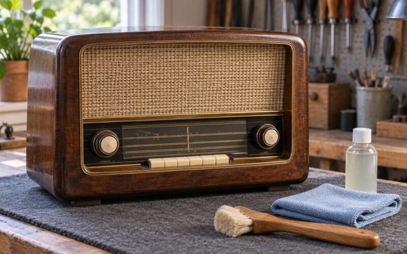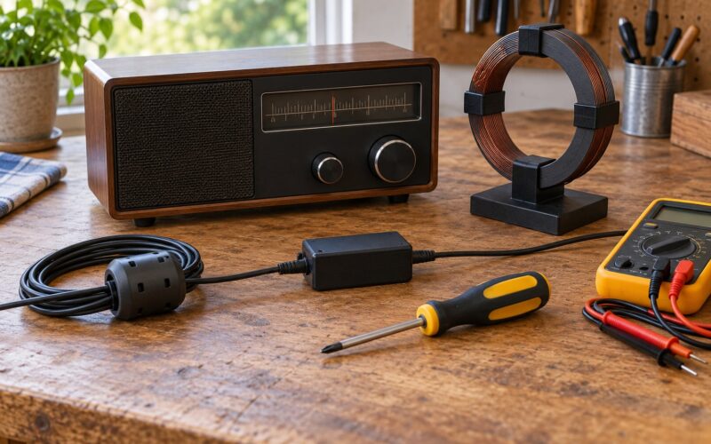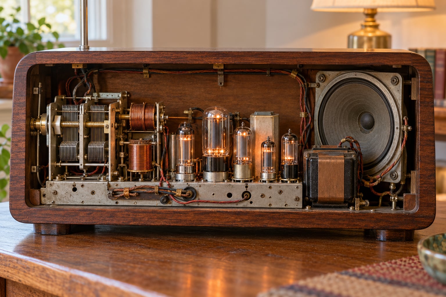
A vacuum tube radio picks up radio waves with an antenna, picks one station out of the air with a tuned circuit, and uses glass valves to turn that tiny electrical signal into something loud enough to drive a loudspeaker. Every sound you hear comes from that path, and once you can trace it, the whole set makes sense.
If you have ever opened the back of a 1940s table radio and found a forest of wires, tubes and coils, this guide is for you. We will walk the signal from the aerial to the speaker one stage at a time, then cover the parts, the power supply and the faults that show up most often.
Table of Contents
- The Short Version: From Radio Waves to Sound
- What Is a Vacuum Tube Radio?
- The Main Parts of a Vacuum Tube Radio
- How the Signal Travels Through the Radio
- How the Antenna Captures Radio Waves
- How Tuning Selects a Radio Station
- What Vacuum Tubes Do Inside the Radio
- How the Radio Turns a Signal Into Sound
- Why Vacuum Tube Radios Sound Different
- Power, Heating, and the Vacuum Itself
- Frequently Asked Questions
- Conclusion: Start with the Signal Path
The Short Version: From Radio Waves to Sound
A vacuum tube radio works by converting radio waves into an electrical signal, selecting one frequency from the many arriving at the antenna, then using heated vacuum tubes to amplify that signal and recover the audio riding on it. A detector strips the audio back off the carrier wave, an audio stage amplifies it, and an output tube pushes it through a transformer into the loudspeaker, which turns the current back into sound waves.
The main parts are the antenna, the tuning coils and variable capacitor, the tubes, the output transformer, the speaker and the power supply that feeds them. A receiver only ever listens. A transmitter does the opposite job: it generates a carrier and modulates it, then drives an antenna hard enough to put real power into the air. Knowing which box you are looking at saves a lot of confusion.
What Is a Vacuum Tube Radio?
A vacuum tube radio is an analog receiver that uses valves — sealed glass envelopes full of gas or a vacuum — to control the flow of electrons. Inside each one, a heated cathode throws off electrons, a control grid regulates how many get through, and a positively charged anode collects them. Change the voltage on that grid and you change a large current, which is how a tiny radio signal becomes a loud one.
That is the whole trick, and it is why we call them valves in Britain. The tube is a controllable valve for electricity, first put to work in a diode by John Ambrose Fleming in 1904 and turned into a real amplifier by Lee de Forest with the triode in 1906. Thomas Edison’s observation in 1880 that current would flow across a gap near a hot filament — the Edison effect — was the raw material both men worked from.
A modern transistor radio does the same job with a solid-state device that has no heater, no glass and no warm-up. Software-defined and internet radios take the signal through a chip and out to a speaker or a network stream instead of through tuned coils. The outcome is the same: a speaker moves. What differs is what happens in the middle.
Why the technology is tied to classic analog receivers
Tube sets are associated with analog listening for two practical reasons. They respond to the signal continuously, with no sampling and no codec, and their tuning is done by physically moving metal. Turning the dial of a 1938 receiver sweeps a shaft across a bank of contacts and swings a variable capacitor, so the station selection is mechanical and audible.
The Main Parts of a Vacuum Tube Radio
Eight parts do nearly all the work. Here is what each one is responsible for, and what changes when you touch the dial or the volume knob.
| Part | Job it does |
|---|---|
| Antenna | Converts incoming radio waves into a tiny electrical signal. |
| Tuner (coils plus variable capacitor) | Resonates at one chosen frequency and rejects the rest. |
| RF amplifier tube | Boosts the weak selected signal before anything else touches it. |
| Detector tube or section | Recovers the audio from the modulated carrier wave. |
| Audio amplifier tube | Raises the recovered audio to a workable level. |
| Output tube and output transformer | Delivers current to the loudspeaker coil at the right impedance. |
| Power supply (rectifier and filter capacitor) | Converts mains AC into smooth DC and keeps hum out of the audio. |
| Speaker | Turns the amplified audio current back into sound in the air. |
When you turn the tuning dial, only the tuner changes. A shaft moves the plates of the variable capacitor, the resonant frequency of the tuned circuit follows, and a different station lands on that frequency. The rest of the radio keeps running exactly as it was.
When you turn the volume control, on an early set you are usually changing the grid bias on the first audio tube rather than changing a modern volume encoder. Turn the knob and the audio stage passes more or less of the signal downstream. On many sets the tone control sits on the same path, using a capacitor and resistor to roll off the treble.
How the Signal Travels Through the Radio
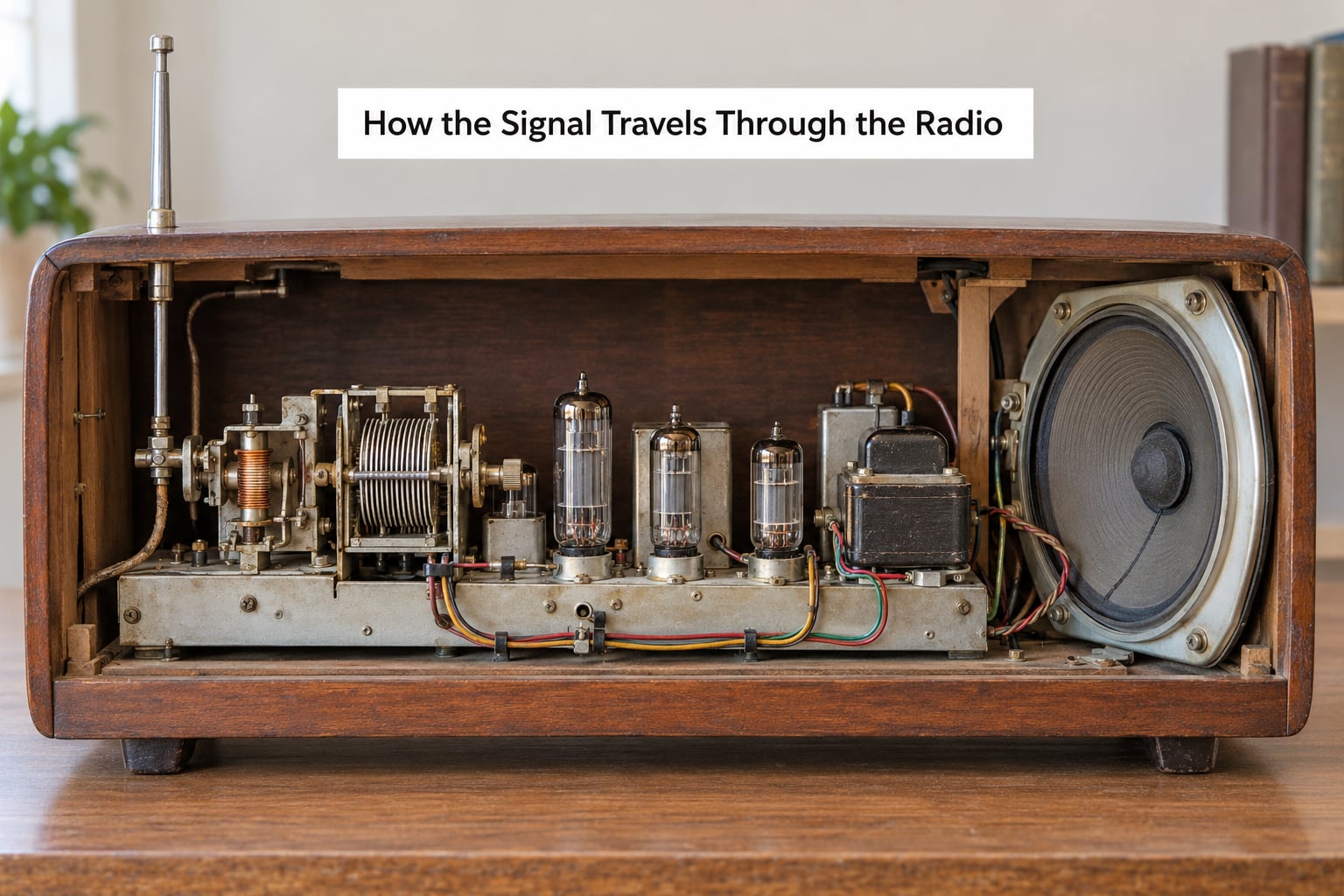
Here is the full chain in order. Every arrow is a real change to the signal.
- Antenna — many stations superimpose their fields on the same wire, each as an alternating voltage at its own frequency and each vanishingly small.
- Tuner — the coil and variable capacitor form a tuned circuit that responds strongly to one frequency and barely to the rest.
- RF amplifier — a tube stage that adds gain at radio frequency, pulling the wanted station out of the noise floor.
- Detector — a diode or triode section that follows the carrier’s peaks and troughs, dumping the audio back out.
- Audio amplifier — a voltage gain stage, usually a triode, that raises the recovered audio without needing to move much current.
- Output stage — a power triode or beam tube that supplies the current swings the loudspeaker needs, matched by the output transformer.
- Loudspeaker — a cone on a coil in a magnetic field, so audio current becomes air movement you can hear.
Notice what is not in that list. Nothing in a receiver decides what to broadcast; it only picks, amplifies and reproduces. And nothing after the detector is still a radio-frequency signal. The moment the detector does its job, the audio path is just audio — which is why the same output stage design appears in radios, record players and guitar amplifiers alike.
How the Antenna Captures Radio Waves
An antenna is a conductor that intercepts an electromagnetic wave and develops a small alternating voltage along its length. That is the entire conversion: no magic, just a wire whose electrons are pushed back and forth by the passing field. A typical AM set picks up a fraction of a millivolt, which is why the RF stage exists.
Antenna length matters because a wire works best when it matches the wavelength it is trying to receive. A long wire couples well to lower frequencies; a short loop works better for shortwave and higher bands. Loop antennas pick up the magnetic part of the wave and are far less affected by local electrical noise, which is why they suit shortwave listening in a room full of appliances.
Location and wiring change how much arrives at the tuner. Keep the lead away from the chassis wiring, do not run it alongside the mains cord, and check that the ground connection to the signal ground is sound. Interference from a dimmer switch, a light dimmer or a switching power supply often shows up as a buzz that changes when you touch the aerial lead, which is a clue worth chasing before blaming the tubes.
How Tuning Selects a Radio Station
Tuning works on resonance. An inductor and a capacitor connected together have a natural frequency where they exchange energy efficiently, and a signal arriving at that frequency drives a much larger current through the circuit than one arriving anywhere else. Change the capacitance and the natural frequency moves with it.
That is the whole mechanism behind the dial. Inside a typical AM set, a variable capacitor with interleaved plates rotates as you turn the knob. The overlap between the fixed and moving plates sets the capacitance, the tuned circuit’s resonant frequency follows, and the station sitting at that frequency suddenly becomes loud. Nearby stations are rejected only so well as the coil’s bandwidth allows, which is why a crowded dial sounds fuzzy between strong local stations.
In a superheterodyne receiver the dial does something different and cleverer. The tuned circuit picks up the station, then a local oscillator generates a second frequency and a mixer tube produces the difference between the two. That difference, the intermediate frequency, is fixed for the whole band, so one set of sharply tuned coils handles every station. It is the architecture that made reliable broadcast listening practical from the early 1930s onward.
A regenerative receiver takes a different route. It feeds a little of the RF output back into the input, which sharpens selectivity and adds gain to the point where a single transistor’s worth of signal gets a fraction of a volt. Owners of these sets often describe the moment it starts as magic. Push the feedback one step too far and the circuit oscillates instead of amplifying, producing the characteristic rising squeal that everyone remembers from early shortwave sets.
What Vacuum Tubes Do Inside the Radio

Thermionic emission is the release of electrons from a hot metal surface. A heater filament, or an indirectly heated cathode sleeve, is brought up to temperature so that electrons boil off its coating. The evacuated glass envelope lets those electrons travel freely instead of colliding with air molecules.
A triode adds a control grid between cathode and anode. The grid sits closer to the cathode, so a small negative voltage on it repels electrons and cuts plate current, while a positive swing releases more of them. Because the grid draws almost no current, a very small input voltage swings a much larger current in the plate circuit — that ratio is the amplification factor, and it is the entire reason the tube was useful.
| Tube type | Electrodes | Job in a radio | Typical numbers |
|---|---|---|---|
| Diode | Cathode and anode | Rectifies mains into DC in the power supply; also detects AM in simple sets. | 5U4, 5Y3, 1A3 |
| Triode | Adds a control grid | Voltage amplification, audio gain stage, output stage, oscillator. | 6A8, 6J5, 42 |
| Tetrode | Adds a screen grid | RF amplification with lower interelectrode capacitance for higher frequencies. | 6D6, 6L6 |
| Pentode | Adds a suppressor grid | RF and IF amplification with the gain and isolation a crowded band needs. | 6E5, 6BA6, 1A4 |
Extra grids exist for a reason. Adding the screen between control grid and anode cuts down the capacitance between them, so a tube built that way keeps working at frequencies where a triode starts to misbehave. That is why a 1938 set uses pentodes in the RF and IF positions while a 1931 set uses triodes throughout, and it is why replacing a pentode with a triode “to improve” the sound is a good way to get instability.
Some sets use one glass envelope with several internal sections stacked inside, so a single 6E5 does the work of three tubes. People who own these often recognise 6E5, 6D6 and 5Y3 numbers out of a 1940s chassis the same way they recognise engine sizes on a car.
How the Radio Turns a Signal Into Sound
What arrives at the antenna is a carrier wave with information folded into it. For AM broadcast, the audio rides on the amplitude: the carrier’s peak swings up and down in step with the sound wave, around 1,000 kilohertz of carrier that never changes. The detector’s job is to follow those swings and reproduce them as a varying voltage at audio frequency.
A diode detector does this on its own — it conducts on the positive half of the carrier and blocks the negative, so the output follows the envelope. A grid leak detector does it with a triode, letting the audio develop across a resistor and capacitor in the grid circuit. Either way, what comes out is audio that matches what went into the transmitter.
FM works differently enough to deserve its own note. The carrier stays at a constant amplitude and the information sits in tiny frequency deviations, so a simple diode throws the variation away. An FM receiver needs a discriminator stage to convert the frequency swings back to audio, and a limiter to clip off noise and stray amplitude variation before that. Sets that are AM-only genuinely cannot receive FM; the detector stage simply is not built for it, which is the usual answer to a set that plays AM but stays silent on FM.
The recovered audio then meets the audio gain stage and the output tube. The output transformer matters as much as the tube: it steps the voltage up and the current down to match the loudspeaker voice coil, and it blocks the direct current in the plate circuit from flowing through the speaker and magnetising its cone. Get that ratio wrong and the speaker distorts or runs hot no matter how good the tube is.
Why Vacuum Tube Radios Sound Different
The warmth people associate with tube sound is a real measurement wrapped in loose language, and it is worth separating the two. The tube’s most audible characteristic is that it compresses rather than clips. Push a triode hard and its plate current bends smoothly into a flattened curve rather than shearing off at a hard ceiling, so peaks get tamed instead of harshly folded over.
Second, distortion here is mostly harmonic rather than odd-order. Harmonics fall at multiples of the fundamental, which the ear hears as thickness and presence rather than as fuzz. Third, most small tube sets have narrow audio bandwidth. A 5 inch speaker in a wooden cabinet rolls off well below 10 kHz and above 4 kHz, and that restricted range changes the character more than any component upstream of it.
None of this means a tube radio is automatically more pleasant. A worn set with tired paper capacitors, a mismatched speaker and a tired output transformer will sound worse than a decent transistor radio, and those three things are far more audible than the difference between a triode and a pentode. The warmth claim mostly holds when the set is in good order and the comparison is against a small transistor speaker doing the same job.
Power, Heating, and the Vacuum Itself
Everything above assumes DC at the right voltage. A tube set runs on mains electricity, and the power supply is the part most often blamed for faults it did not cause. The rectifier tube passes current through one half of the AC cycle only, giving a pulsating DC. The filter capacitor smooths that ripple, and whatever ripple survives is added to the audio as hum.
Loud hum is the classic power supply symptom, and people chasing it on r/VintageRadios and r/AskElectronics usually end up in the same place: aged electrolytic filter capacitors. They dry out over decades and stop doing their job, so the B+ line sags and humbles the whole chassis. One 5Y3 or 5U4 rectifier and two or three filter capacitors will restore the supply on a set that has not been powered in years.
Warm-up time is the other thing beginners mistake for a fault. Heaters have to reach temperature before the cathode emits usefully, and a chassis full of valves takes 10 to 30 minutes to behave like itself. Sound that is thin and quiet at first and settles into full volume later is normal operation, not a broken set.
The vacuum matters because air molecules would collide with the electrons and scatter them. A hard vacuum keeps the electron stream clean, and a small metal mirror called a getter, flashing inside the glass when the tube is made, absorbs any gas that remains. A cloudy or milky tube has lost that protection and should not be trusted with power.
That same vacuum means a real safety problem. Rectifier and output plates sit at voltages high enough to be dangerous, and on an AC-operated set the chassis may be connected directly to one leg of the mains. Restorers on edaboard and the ham boards are consistent about this: bring a set up slowly on a variac or a dim-bulb tester, isolate it from the mains, and never work on it live unless you already know exactly what you are doing.
Frequently Asked Questions
Can you explain how vacuum tubes work?
A heater warms a cathode until it emits electrons, thermionic emission. A control grid sits between the cathode and the anode and regulates how many electrons reach the anode. Because the grid draws almost no current, a small voltage change on it produces a large change in plate current, so the tube turns a tiny input signal into a much larger one.
What replaced vacuum tubes in the 1950s?
The transistor. The first working transistor was demonstrated in 1947 and transistors reached consumer radios in the mid-1950s. They needed no heater, produced almost no heat, were tiny and cheap in volume, and worked instantly. Portable transistor radios became practical because of them, and tube sets moved to the specialist hi-fi, industrial and broadcast-transmitter markets.
How does a vacuum tube amplifier work?
The audio signal is applied to the control grid of a gain tube, and the grid’s changing voltage modulates the plate current flowing through the anode circuit. A load resistor or transformer converts that current change into a larger voltage change. Cascading stages gives enough voltage and current swing to drive the loudspeaker through the output transformer.
How do you fix a radio that turns on but has no sound?
Work in order rather than replacing tubes at random. Check the speaker and its connections first, then the power supply rectifier and filter capacitors, then the audio and output tubes, then the antenna and tuner wiring. Use a tube tester rather than guessing, and bring the set up slowly on a variac because aged capacitors often fail short and blow a fuse.
Why does my radio work on AM but not FM?
AM detection and FM detection are different circuits. AM needs a diode or grid leak to follow the carrier envelope, while FM needs a discriminator to turn frequency deviations back into audio, plus a limiter to clean the signal up. An AM-only chassis has no discriminator stage at all, so it hears the FM carrier as noise and stays silent.
What are some common applications of vacuum tubes?
High-power radio transmitters and broadcast equipment, high-fidelity audio amplifiers, guitar amplifiers, industrial heating and welding, radar and magnetron tubes for cooking, medical imaging and radiation therapy equipment, and scientific instruments. Cathode ray tubes for television and computer displays were a major application until flat panels displaced them.
Conclusion: Start with the Signal Path
Remember the chain and a tube radio stops being a mystery box. The antenna catches every station at once, the tuner selects one frequency, the RF stage lifts it above the noise, the detector pulls the audio off the carrier, the audio and output stages make it powerful enough, and the speaker turns it back into sound. Every fault you will ever meet sits somewhere along that line.
So when you take the back off an old set, inspect in the order of the signal path. Start with the antenna connection and its ground, then the power supply, where a tired filter capacitor or rectifier causes hum and low volume. Check the tubes properly with a tester rather than by appearance, then the tuning capacitors and the band-switch contacts, and finally the speaker and output transformer.
Give it 15 minutes of warm-up before judging it, and treat the high voltage inside as live at all times. Trace the path once with a pencil on the chassis and the whole receiver stops being vintage magic and starts being a set of ordinary electrical stages.