A crystal radio set needs no battery, no power supply and no amplifier. The incoming AM signal makes the sound itself, so learning how to build a crystal radio set comes down to winding a coil, wiring in a germanium diode and a high-impedance earphone, then finding a good aerial and a real ground. It takes an afternoon and teaches more radio physics than most people get anywhere else. Plenty of beginners still start electronics this way in 2026.
The circuit has four parts and no clever tricks, but two of them punish laziness: a short aerial indoors and a ground that is not actually the earth. Get those right and a strong local station will come through faintly but unmistakably.
Table of Contents
What You Need to Build a Crystal Radio Set
Every item below is cheap, and most electronics suppliers or hobby sellers stock them. Nothing here runs off mains or off a battery, so the only real safety points are about height and digging.
- Enameled magnet wire, 22-26 AWG, about 75 ft (23 m) for the tuning coil. Thirty-gauge is easier to wind; 22 gauge gives a stiffer coil that holds its shape.
- A 1N34A germanium diode as the detector. Germanium has a forward drop of roughly 0.3 V, and that low drop is the whole reason it beats a silicon diode here.
- A high-impedance earphone, 2000-8000 ohm (2k to 8k). This is the single most common reason a first build fails: modern low-impedance earbuds draw too much current to give anything back.
- A capacitor around 150 pF for a fixed single-station design, or an air-gang variable capacitor (10-365 pF) if you want to sweep the band.
- Insulated aerial wire, 20-50 ft (6-15 m) to start. For real reception most builders run 30 m (100 ft) or more, as high as you can safely get it.
- A coil former: a cardboard tube, a large film canister or a toilet roll works fine.
- A ground connection: a copper pipe strap, a metal cold water pipe, or a short copper stake driven into damp soil.
- Small hand tools: sandpaper or a needle for scraping enamel, crocodile clips, insulating tape, small pliers and a continuity tester if you have one.
Optional extras: a 47k-ohm resistor in series with a piezoelectric earphone, an audio transformer with a 1000-2000 ohm primary and a 4-32 ohm secondary, a transistor amplifier for volume, and a wooden base so the set stops being a heap of wire on a table.
Keep the whole thing low voltage and battery-free. Do not climb onto a roof for the aerial, and if you plan to hammer a ground stake into the garden, check for buried services first. In the UK that means calling National Gas before you dig, and staying well clear of any pipe or cable marker you find.
Step-by-Step
The signal path is short enough to hold in your head: the aerial picks up every AM station at once, the coil and capacitor form a tuned circuit that resonates at one chosen frequency and rejects the rest, the diode rectifies the selected signal to pull out the audio, and the earphone turns that audio into sound. Follow the stages in order and you can always tell whether a fault is in the tuner or after it.
Plan the Circuit and Choose a Work Area
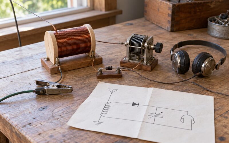
Sketch the circuit before you solder anything. One end of the coil goes to the aerial, the other end goes to one side of the capacitor and to one leg of the diode; the far side of the capacitor goes to ground; the other diode leg goes to the earphone, whose other terminal returns to the coil. That closed loop is the receiver.
Work on a well-lit table with a hard surface, a small vice for the coil former and a mug for the tea you will be drinking. Keep the parts in a small box rather than scattered across the bench, because the one piece you lose is always the diode.
Before wiring anything, scrape a small patch of enamel off both ends of your coil wire and check the continuity across the coil. A reading of a few ohms means the winding is intact; an open circuit means the enamel is not cleaned off or the wire is broken.
Connect the Antenna and Ground
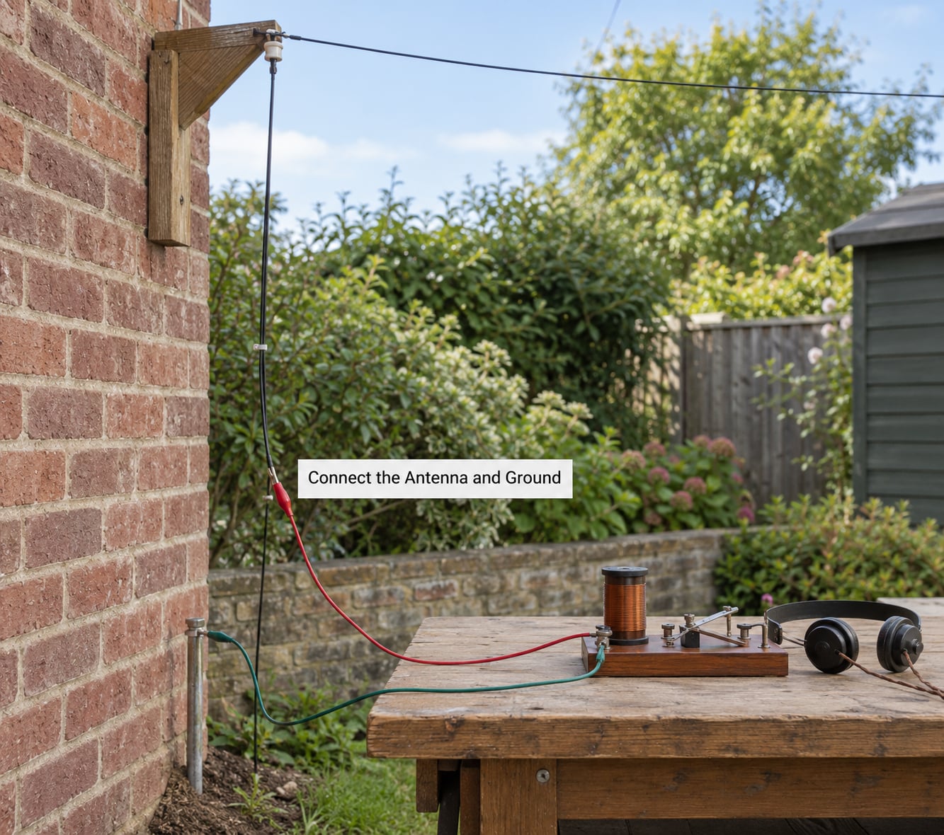
Run the aerial wire as high and as far from buildings as you can. A long-wire aerial strung between a chimney stack and a garden tree is the classic arrangement, and for indoor-only testing a wire near a window frame will prove the set works even if reception is poor.
Choose the ground carefully, because this is where modern houses defeat the standard instructions. A metal cold water pipe is fine, but check whether it turns to plastic where it enters the wall, and only use metal you have confirmed with a continuity check. If it is plastic, use a copper pipe earth strap, a metal gas pipe with the earthing continuity proved, or a short copper stake in damp soil near a fence.
Keep the aerial and ground leads short and twisted together as they run to the set. Long parallel wires act as an unwanted aerial and undo your careful work.
Build the Tuning Coil
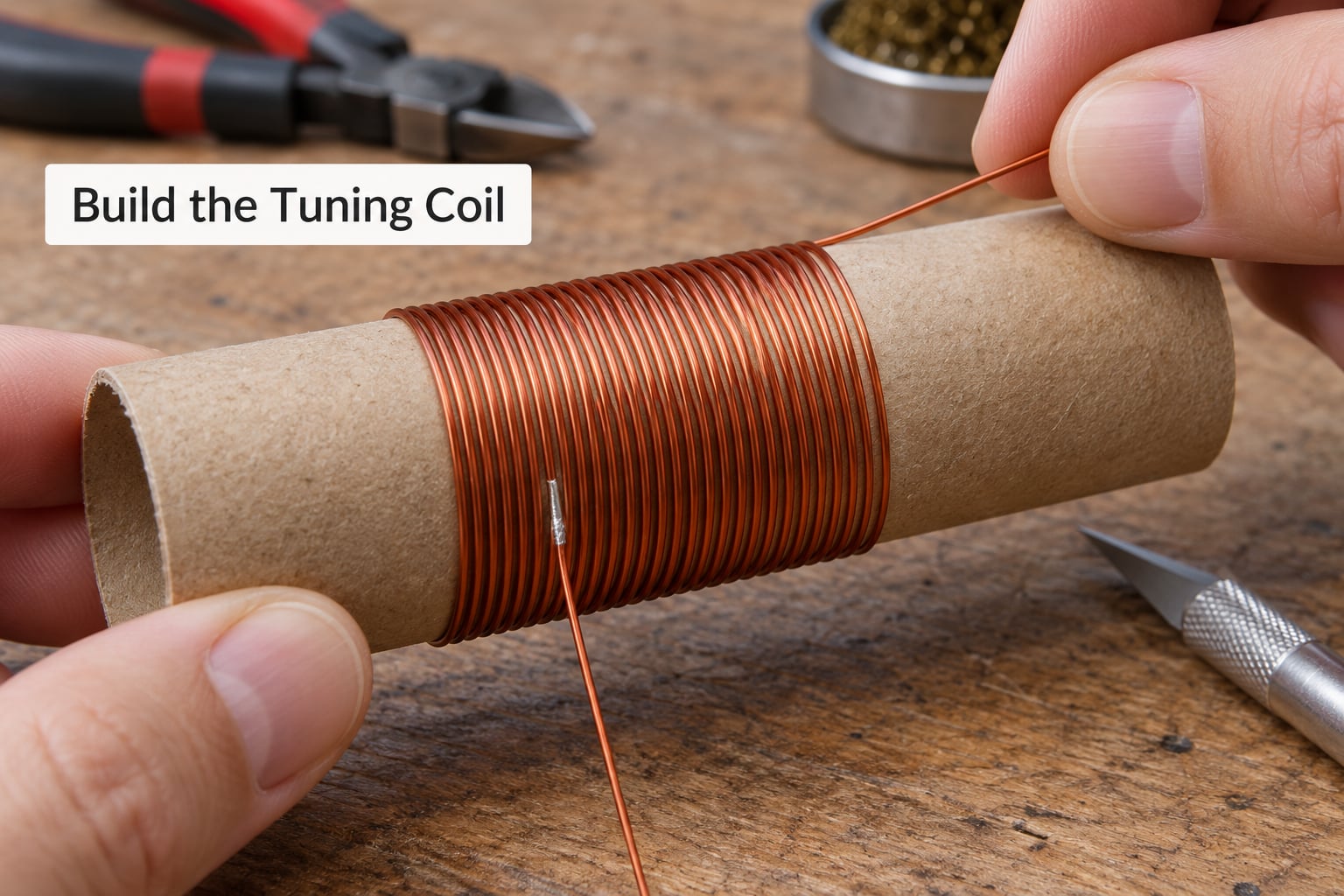
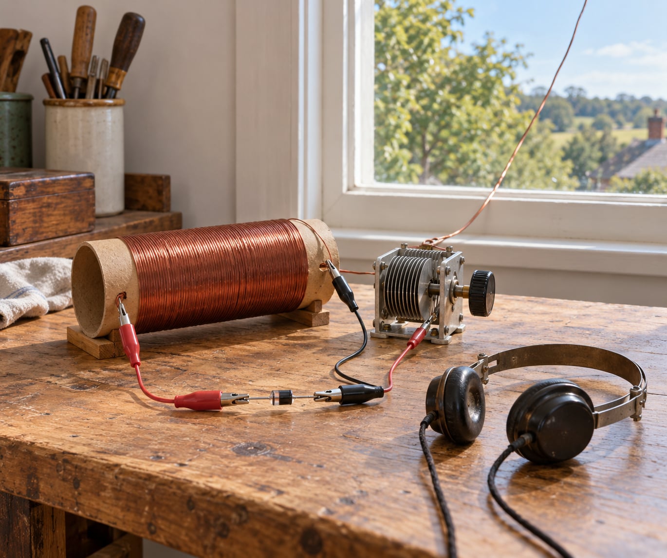
Wind about 60 turns of the magnet wire onto the former in even, side-by-side turns. Keep the tension steady and the turns touching, and leave the last few turns free so the coil slides off without stretching it.
Now decide how you will tune. Two methods work. With a tap, scrape the enamel off a single turn partway along the coil and clip a lead to it; moving the tap changes the inductance and moves the resonant frequency. With a slider, leave a section of the coil unwound enamel and use a sprung wire contact that you slide along it, which gives smoother, continuous tuning.
If you want to size the coil yourself, use the resonance formula:
f = 1 / (2π √(LC))
For the medium wave AM band between roughly 530 and 1600 kHz, a 150 pF capacitor wants a coil inductance between about 65 microhenries and 600 microhenries. A worked example: a coil of 60 turns on a 25 mm (1 inch) diameter former gives roughly 170 microhenries, and with a 150 pF capacitor that lands near 1000 kHz in the middle of the band. Shorten the coil for the top of the band, lengthen it for the bottom.
Wire the Crystal Detector and Headphones
Scrape the enamel from each end of the coil and from the tap or slider contact. The diode’s cathode end, the banded end, connects towards the earphone; the anode goes to the coil and capacitor junction. Getting this backwards still lets current through but loses most of the sensitivity.
Connect the capacitor between that same junction and ground, so the coil and capacitor sit in parallel. That parallel pair is the tuned circuit, and keeping the leads short keeps its Q high.
Now add the earphone. With a 2000-8000 ohm magnetic earphone, the connection is direct: one lead to the diode, the other back to the coil. With a piezoelectric crystal earpiece, put a 47k-ohm resistor in series, because the piezo needs a defined load to produce sound.
If your audio is too quiet to hear across a room, an audio transformer does more than anything else. Feed the coil current through a 1000-2000 ohm primary and take the output from a 4-32 ohm secondary, and the same weak signal suddenly drives low-impedance headphones or a small speaker. If you would rather not wind a transformer, feed the earphone output into the phono input of any stereo amplifier and use that as your loudspeaker.
Test the Crystal Radio Set
Put the headphones on before you touch anything else, then attach the aerial and ground leads with the set physically away from mains-powered equipment. Turn the tuning slider or move the tap slowly from one end of the coil to the other.
With no station, you will usually hear a faint rush of static that rises and falls as you move. When the tuned circuit crosses a station, that static swells and speech appears under it. That swelling noise is the confirmation the circuit works, even before you can make out a single word.
Start in daylight. Local AM transmitters are stronger after dark, when ionospheric propagation adds distance, and several builders report coming back to the same set in the evening and getting two stations where there was none at lunchtime.
Improve Reception and Range
When the set is quiet, the fix is nearly always outside the box. Lengthen the aerial before touching the circuit, raise it higher, and move it away from the house roof and any metal guttering. Then improve the ground: a copper strap on a proven metal pipe or a stake in damp soil will usually deliver more than a new coil ever will.
Work inside the set next. Confirm the diode direction with a multimeter diode test, tighten the tap or slider contact, and check that the coil lead is not being lost under a crocodile clip. Swap a 1N34A for another 1N34A if you have a spare; germanium diodes vary between parts and a poor sample is common.
Finally, think about selectivity. A simple single-tap coil has a wide bandwidth, so two nearby stations overlap into a smear. A variable capacitor narrows that band considerably, and adding a second loosely coupled coil smooths it further. Expect weak, thin audio no matter what, because there is no amplifier in the path.
Common Mistakes
Nearly every failed first build is one of these, and each has a specific correction. Work down the list rather than changing three things at once.
- Absolute silence, no static at all. Usual cause: low-impedance earbuds. Use a 2000-8000 ohm magnetic earphone, or add an audio transformer or amplifier.
- Loud static, no station. Usual cause: aerial too short, too low, or indoors. Run 30 m (100 ft) or more as high as you can, and check that the coil tap has a clean metal contact.
- Static that swells and collapses at one spot. That usually is a station being clipped by too little selectivity. Fit a variable capacitor, or add a loosely coupled second coil.
- Two stations at once. The coil bandwidth is too wide. Reduce the number of turns to raise the resonant frequency, fit the variable capacitor, or separate the stations with a second tuned coil.
- Works in one room, nothing next door. The ground has moved to plastic. Find a section of metal pipe that is genuinely conductive, or drive a copper stake into damp soil.
- Audio was fine, then stopped. Work backwards: test the earphone on another set, recheck the diode direction, and clean the slider contact. A tired ground connection is the usual culprit.
- Used a silicon diode. Its forward drop of around 0.7 V eats most of the signal on a weak station. Fit a 1N34A germanium diode instead.
A few tips that save time. Label every lead as you connect it. Keep the coil, capacitor and tap leads as short as physically possible. And if your local AM band is sparse, accept that one station is a success rather than a failure; a builder on r/amateurradio got a working set with a coil, a capacitor, a diode and an amplifier, and proved the point by hearing exactly one station.
Frequently Asked Questions
Do crystal radios need batteries or electricity?
No. A crystal radio is a passive receiver: all the power for the sound comes from the radio wave itself. Once you have an aerial, a coil, a tuning capacitor, a diode and a high-impedance earphone, there is nothing else to connect. Many people keep one in a drawer as a battery-free emergency receiver.
Why is my crystal radio set picking up only faint sounds?
Faint audio is normal and usually means the set is working rather than broken. To get louder, lengthen and raise the aerial, improve the ground connection, confirm the earphone is 2000-8000 ohm, and add an audio transformer or a small transistor amplifier. Moving the tap or the tuning capacitor onto a stronger local station also helps a lot.
What headphones work with a crystal radio?
A high-impedance magnetic earphone rated between 2000 and 8000 ohm. Modern low-impedance earbuds draw too much current and give you silence, which is the most common reason first builds fail. A piezoelectric crystal earpiece also works, but needs a 47k-ohm resistor in series. Low-impedance headphones need an audio transformer or an amplifier.
How do I find stations with a crystal radio?
With a fixed capacitor, move the tap contact along the coil a turn at a time and listen for the static to swell. With a variable capacitor, turn the knob slowly across the range. The station appears where the noise rises and speech comes through underneath it. Record which tap position or capacitor setting works and mark it on the base.
Can a crystal radio receive AM stations during the day?
Yes, daytime reception works well for local medium wave stations, usually up to roughly 25 miles (40 km) from a strong transmitter, and reception improves at night as the signal reflects off the ionosphere. Long wave stations can travel much further. If you only hear one station, that is a normal result in an area with sparse local AM coverage.
Is it safe to connect an antenna to a crystal radio?
Yes, because the circuit carries no mains power and no battery, so there is no shock risk from the radio itself. The care needed is physical: do not climb onto a roof to run the wire, keep the aerial clear of power lines, and secure it so it cannot fall. Check for buried services before driving a ground stake into a garden.
Conclusion
Start by checking three things: that the coil has continuity, that the earphone is high-impedance, and that the aerial and ground are both real connections rather than hopeful ones. Then tune slowly from one end of the coil to the other and let your ears do the work, because the station announces itself as a swelling of static before any words appear.
Keep the aerial high and well clear of power lines, ground the set to metal you have proved conductive or to a stake in damp soil, and expect thin, quiet audio rather than a broadcast-quality signal. That faint voice coming out of a set with no battery in it is the whole point of the project.